

 English


How to solve the optical power alarm of optical module in equipment?
When we use the optical module, sometimes improper use will lead to abnormal operation of the optical module, so in this case, how should we solve it? Today, ETU-LINK will tell you an answer. When the optical power of the optical module is too high or too low, how to diagnose the causes and the corresponding solutions.
Taking Huawei switch as an example, when the optical power alarm occurs, the following information will appear:
1. BASETRAP_1.3.6.1.4.1.2011.5.25.129.2.17.1hwOpticalPowerAbnormal//
Alarm is sent when the optical module sends or receives abnormal power
2. ENTITYTRAP_1.3.6.1.4.1.2011.5.25.219.2.4.5hwOpticalInvalid136193 //
Optical module sends high optical power alarm
3. ENTITYTRAP_1.3.6.1.4.1.2011.5.25.219.2.4.5hwOpticalInvalid136194 //
Optical module sends low optical power alarm
4. ENTITYTRAP_1.3.6.1.4.1.2011.5.25.219.2.4.5hwOpticalInvalid136195 //
Alarm of high optical power received by optical module
5. ENTITYTRAP_1.3.6.1.4.1.2011.5.25.219.2.4.5hwOpticalInvalid136196 //
Alarm of low optical power received by optical module
When there is an optical power alarm, we don't have to panic. We can first see the possible reasons for the abnormal optical power. Generally, the abnormal optical power is caused by the following reasons.
1. The model and wavelength of a-end and b-end optical modules are inconsistent;
2. The optical module is not tightly inserted or the optical fiber is faulty;
3. The optical fiber is too long or the link loss is too large;
4. Abnormal opposite end luminous power;
5. Optical module failure.
Below ETU-LINK will check the reasons one by one according to the reasons listed above until the specific reasons are found.
1. Let's first see whether the wavelength parameters of the optical module at the a-end and b-end are consistent. At this time, we can execute the display transceiver [ interface interface-type interface-number | slot slot-id ] [ verbose ] command, and then the screen will display the information of the optical module on the device interface. If the wavelength is inconsistent, we need to replace the optical module with the same wavelength;

2. Check whether the connection of the link is normal. At this time, we can plug in the optical fiber and optical module again to determine whether the contact is bad. At the same time, we can check whether the fiber connector is polluted, and then connect the link after cleaning the end face of the optical fiber;
3. Check the length of the optical fiber. The length of the optical fiber must be less than the transmission distance supported by the optical module (query the instruction in step 1). Otherwise, it is necessary to reduce the length of the optical fiber or replace the optical module supporting a longer distance;
4. Check whether the optical power of the optical module of the opposite equipment is normal, and the emission light power value shall not be less than the minimum optical power value;
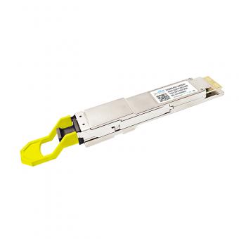
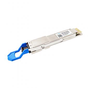
5. Confirm the optical fiber type of optical transceiver. The single mode optical module shall be equipped with single-mode optical OS2 patch cord, the color of OS2 patch cord is yellow, multimode optical module shall be equipped with multi-mode optical OM2\OM3\OM4 patch cord, the color of OM2 patch cord is orange, the color of OM3 patch cord is lake blue, and the color of OM4 patch cord is violet.

6. Check the model and manufacturer of the optical module. Although the wavelength of the optical module is the same, the optical power index of the optical module itself is not the same due to the different design of each manufacturer, which leads to the phenomenon of power alarm when docking. The user can replace the optical module of the same manufacturer.
The above is the optical power alarm solution introduced by ETU-LINK. We need to pay attention to avoid the above problems when using the optical module to ensure the normal operation of the optical module. If you want to know more about the use of the optical module, you can refer to the relevant articles of ETU-LINK.
Categories
New Blog
Tags
New Products
For inquiries about our products or pricelist, please leave to us and we will be in touch within 24 hours.


 Factory: Right Side Of 3rd Floor, No. 102 Building, Longguan Expressway, Dalang Street, Longhua District, Shenzhen
Office: Floor 4, Building 4, Nanshan Yungu Phase ll, Taoyuan Community, XiliStreet,Nanshan District, Shenzhen
© Copyright: 2024 ETU-Link Technology CO ., LTD All Rights Reserved.

IPv6 network supported
Friendly Links:
易天官网

