English


Analysis of Device Damage Caused by Direct Installation of Long-Distance Optical Modules
In fiber-optic communication systems, long-distance optical modules, due to their high transmit optical power, are highly susceptible to damage to receiving devices when directly connected to shorter optical fibers. This article analyzes the mechanisms of optical power overload, typical damage scenarios, and protective measures, providing technical references for engineering practice.
I. Physical Mechanism of Optical Power Overload
The transmitted optical power of long-distance optical modules (such as 40km/80km/120km specifications) is generally higher than that of short-haul modules, typically reaching +2dBm to +5dBm. When such modules are directly connected to short-haul optical fibers (such as links under 10km), the optical power at the receiver can far exceed the device's tolerance limit due to the fiber's insufficient attenuation (single-mode fiber has an attenuation coefficient of only 0.4dB/km at a wavelength of 1310nm).
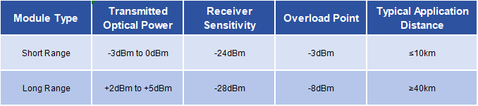
Key Parameter Comparison
When a 40km module is directly connected to a 2km optical fiber, the fiber attenuation is only 0.8dB (2km x 0.4dB/km), and the optical power at the receiving end can reach +1.2dBm to +4.2dBm, far exceeding the -8dBm overload threshold of the receiving assembly (ROSA). This causes a sharp increase in photocurrent, leading to overheating and breakdown of the PN junction, resulting in permanent damage.
II. Analysis of Typical Damage Scenarios
1. Disaster Caused by Direct Loopback Testing
A data center, a loopback connection was made without inserting an attenuator, resulting in a high optical power of +4dBm at the receiving end. The test revealed: black burn marks on the ROSA component; the receiving current abnormally increased to 500mA (normal value ≤100mA); and the module IBias If the ADC value remains at 0, it indicates that the power supply circuit at the transmitting end is damaged.
Root cause analysis: The loopback test causes 100% of the transmitted optical power to be returned to the receiver, resulting in a superposition effect that causes optical power to accumulate. If the module's transmitted optical power is +3dBm, the actual optical power at the receiver after the loopback reaches +6dBm, exceeding the ROSA overload point of -8dBm.
2. Short-distance Fiber Optic Misconnection Incident
When deploying a metropolitan area network, a carrier mistakenly connected an 80km long-haul module to a 5km optical fiber link. After three hours of operation, the RSSI value at the receiving end remained at 0, the module housing temperature rose to 65°C (normal value ≤45°C), and the demodulated bit error rate reached 10⁻³ (normal value ≤10⁻¹²).
Disassembly revealed: cracks on the ROSA chip surface and a breakdown of filter capacitor C12 (reference power circuit). The incident resulted in direct economic losses of 120,000 yuan and disrupted regional services for four hours.
III. Systemic Protection Plan
1. Precise Power Budget Control
Implement a three-step approach to power management:
① Pre-connection test: Use an optical power meter to measure the optical power at the transmitter. If it exceeds the +3dB margin of the receiver sensitivity, immediately enable the attenuation solution.
② Dynamic attenuation adjustment:
Links below 40km: Insert a fixed attenuator (such as 5dB FC/PC type)
For links longer than 40 km, use an adjustable optical attenuator (EVOA) with a 3dB adjustment margin.
③ Online monitoring: Read module diagnostic information in real time through the SNMP protocol, and trigger an alarm when the received optical power is greater than -10dBm.
Installation Prohibition List:
① Do not directly connect optical fibers without testing the optical power;
② Do not use optical fiber direct connection for loopback testing;
③ Do not use long-distance modules for links below 10 km.
Recommended Operating Procedures:
① After inserting the module into the device, read the initial optical power using the display transceiver diagnosis interface command.
② Before connecting the optical fiber, use the adjustable attenuator to adjust the received optical power to the range of -15dBm to -20dBm.
③ Perform optical power back-off tests quarterly to ensure stable attenuator performance.
3. Device Selection Criteria
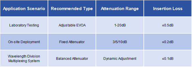
Attenuator Selection Matrix
Attenuators with MPO interfaces are preferred, as they can reduce insertion loss by over 40%. For 400G systems, integrated attenuation modules are recommended to reduce the number of discrete device connection points.
IV. Emergency Response to Accidents
When an optical power overload occurs, immediately perform the following actions:
1.Power-off protection : Disconnect the module from power to prevent continued overheating.
2.Damage assessment : Visually inspect the ROSA end face for blackening; use a multimeter to measure the resistance of the VCC pin to ground (normal value > 10kΩ); and read the DMI register value using the debug software.
3.Graded action : Mild overload (received optical power < -5dBm): Replace the attenuator and observe for 24 hours. Severe overload (received optical power > 0dBm): Replace the entire optical module.
Directly connecting long-distance optical modules over short distances essentially results in a loss of control over optical power budget management. By implementing a three-tiered protection system consisting of "pre-testing - dynamic adjustment - continuous monitoring," the component damage rate can be reduced from the industry average of 12% to below 0.3%. Operators are advised to explicitly require suppliers to provide optical power protection solutions in equipment procurement contracts and include this as a mandatory clause during project acceptance.
For inquiries about our products or pricelist, please leave your information with us and we will be in touch with in 24 hours.


 Factory: Right Side Of 3rd Floor, No. 102 Building, Longguan Expressway, Dalang Street, Longhua District, Shenzhen
Office: Floor 4, Building 4, Nanshan Yungu Phase ll, Taoyuan Community, XiliStreet,Nanshan District, Shenzhen
© Copyright: 2026 ETU-Link Technology CO ., LTD All Rights Reserved.

IPv6 network supported
Friendly Links:
易天官网