English


Analyzing Abnormal Situations During Installation and Use of Optical Module
As core components of optical communication systems, the proper installation and use of optical modules directly impacts network stability. This article systematically identifies common anomalies during optical module installation. Combining hardware principles with practical experience, it provides step-by-step solutions and key considerations to help engineers efficiently troubleshoot.
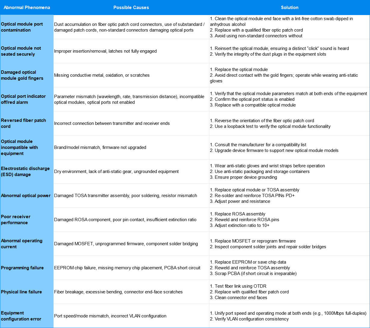
The following table lists common abnormal phenomena and solutions during the installation of optical modules:
1. Dust prevention and cleaning: Details determine success or failure
1) Unused protection: When an optical module is not in use, a dust cap must be installed to prevent dust from entering the port and causing poor contact.
2) Cleaning specification: Use special wiping paper or dust-free cotton swab to wipe the end face in the same direction. Do not rub back and forth to prevent scratches.
2. Standardize operating procedures: Reduce human errors
1) Check before insertion: Make sure the dust plug in the device slot is intact to prevent foreign objects from entering.2) Insertion and removal tips: When inserting, align the optical module with the slot and gently push until it locks into place; when removing, pull out the lever first and avoid violent operation.
3) Storage environment: Optical modules should be stored in anti-static blister boxes to avoid direct contact with metal objects.
3. Compatibility Verification: A Must for Cross-Brand Interconnection
1) Compatibility List: Before interconnecting devices of different brands , be sure to consult the manufacturer to obtain the optical module compatibility list to avoid parameter mismatches.2) Firmware upgrade: New optical modules require the device firmware to be upgraded to the latest version to ensure protocol support.
3) Test verification: After a small-scale pilot deployment, test link performance using a bit error meter to confirm there is no packet loss or bit errors.
4. Electrostatic Discharge (ESD): The Invisible Killer
1) Environmental control: The operating environment humidity should be maintained at 30%-70% to avoid static electricity caused by dryness.2) Be well-equipped: wear anti-static gloves and wrist straps, and use anti-static packaging and storage containers.
3) Device grounding: Ensure that the device is well grounded to prevent static electricity from being transferred to the circuit board through the optical module.
5. Troubleshooting priority: From easy to difficult
1) Hardware level: Prioritize checking the physical status of optical modules, fiber optic patch cords, and device ports (such as contamination, damage, and tightness of insertion).2) Configuration level: Verify parameter matching (wavelength, rate, mode), port status, and VLAN settings.
3) Log level: Locate the alarm code in the device log (for example, 0x00000110 indicates an optical module failure) and analyze the cause in conjunction with the manufacturer's documentation.
1. Prevention first: Reduce the occurrence of failures through standardized operations and regular maintenance.
2. Layered troubleshooting: Locate the problem step by step in the order of "hardware-configuration-log".
3. Record archiving: Establish a fault case library to provide reference for subsequent operation and maintenance.
This article helps engineers quickly identify optical module installation issues and take targeted measures to restore network operations. We recommend saving this article as a tool document for easy reference.
For inquiries about our products or pricelist, please leave your information with us and we will be in touch with in 24 hours.


 Factory: Right Side Of 3rd Floor, No. 102 Building, Longguan Expressway, Dalang Street, Longhua District, Shenzhen
Office: Floor 4, Building 4, Nanshan Yungu Phase ll, Taoyuan Community, XiliStreet,Nanshan District, Shenzhen
© Copyright: 2026 ETU-Link Technology CO ., LTD All Rights Reserved.

IPv6 network supported
Friendly Links:
易天官网