English


Server and switch connection and campus network construction solution
What Is a Server and How Does It Connect to a Switch?
Server-switch interconnection and campus network deployment are core networking scenarios in enterprise, education, and data center communication. This article provides complete solutions for server-switch connection, high-speed optical interconnection, and reliable campus network construction with standard-compliant components and best practices. Speaking of the server, in fact, it is a little similar to the computer we use in daily life, which is the equipment to provide computing services. The composition of the server includes processor, hard disk, memory, system bus, etc. As the server needs to respond to the service request and process, generally speaking, the server should have the ability to undertake and guarantee the service.
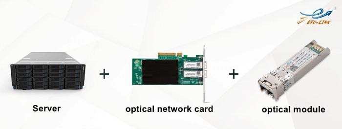
Server has single, double, four, eight options, it correspondingly represents the number of loaded CPU, such as four server has four CPU processors, more lines of the server means the server data processing capacity is stronger. Usually there is no optical port on the server motherboard, only the bus interface, interface standards are PCI, PCI-X, PCI-E, etc., these sockets are inserted into the optical network card, and then through the optical network card inserted into the optical module and optical patch cord to achieve the connection with the switch. Servers rely on PCIe network adapters (NICs) to provide optical ports, supporting 1G, 10G, 25G, 40G, 100G high-speed transmission for stable interconnection with switches.
What Are Common Switch Port Types for Server Interconnection?
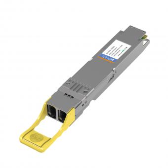
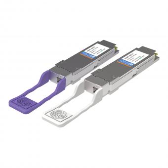
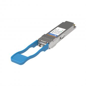
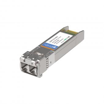
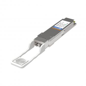
Switch is an electrical signal forwarding network equipment, it can give any two network nodes to provide independent electrical signal links. The common port types on switches are Gigabit SFP, 10 Gigabit SFP+, 25G SFP28, 40G QSFP, 100G QSFP28, etc.
These ports support SFP/SFP+/QSFP+/QSFP28 optical modules, DAC cables, and AOC cables for flexible high-speed connection between servers and switches in campus networks and data centers.
How to Connect a Server to a Switch?
Next, ETU-Link will introduce how the server connect with the switch.
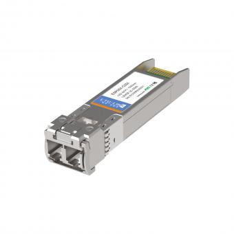
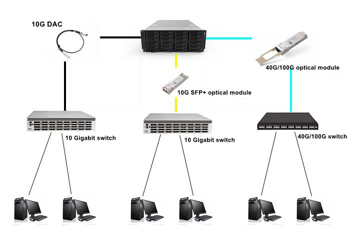
Usually, the network topology scheme is to connect Ethernet to the firewall, and then connect the firewall to the core router, after that, the core router connect the Web server. We can insert the optical fiber network card matching the port rate of the switch into the server according to the need. Take 10G optical fiber network card as an example. ETU-Link's 10G DAC/AOC or 10G SFP+ optical module with fiber patch cord can be used to connect to the 10G SFP+ uplink port of the Gigabit access layer switch, and then the downlink Gigabit port can be connected to the computer and other user equipment.
Three mainstream connection modes:
1) DAC Cable: Short-distance, low-cost cabinet interconnection
2) AOC Cable: Longer distance, anti-interference
3) Optical Module + Patch Cord: Long-distance, high-stability transmission
Campus Network Construction Solution for 20,000-User Scenarios
We can take building the campus information portal as an example. The information portal consists of portal interface management, unified identity authentication service and application management service. This scheme mainly includes the Web publishing subsystem to realize load balancing, the database double-machine high availability subsystem, the FC-SAN storage and backup subsystem, and the hardware security firewall. Considering the reliability and stability of the system, for the storage system, it is suggested to adopt the redundant structure to improve the overall reliability of the system, configure the online all-fiber disk array with dual controllers and the redundant fiber switch.
This solution supports high-speed, stable, and scalable campus network services, including online teaching, office automation, resource management, and portal access.
1.Construction of Web publishing subsystem:
Web server is the information release platform of application system. In the multi-layer architecture of application system, the portal website serves as the information publishing layer, providing functions such as information browsing and service positioning. The Web server mainly finish the following work. First, it receives the user access request and keeps the user connected. Then it sends the user access request to the application service and waits for the query processing result of the application service. Finally, the processing result page of receiving application service is provided for users to browse.
When we choose the Web server, we can choose it according to the business forecast data. Based on the estimation of a school of 20,000 people, its SpecWeb2005 value is about 57,000, and it can be equipped with XE CPU, 3TB memory and 16G operating memory.
Web servers use 10G/25G network adapters and connect to core switches via 10G SFP+ modules or DAC cables for high-concurrency access.
2. Construction of dual-machine high-availability subsystem of database:
For a school with a population of 20,000, the TPC-C value for the database server requirement is around 800,thousand yuan. We can choose database servers based on business pressures and application size. In addition, each server is equipped with a dual-port 8GB FC HBA card for connecting to storage devices.
Dual-server high availability ensures zero service interruption and supports automatic failover for critical campus data services.
3. Storage system construction:
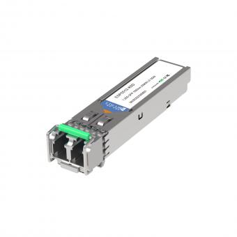
The system design considers the reliability of critical applications and the security of data. The fully redundant FC SAN architecture (2 FC HBA cards, 2 fiber switches and redundant disk array controllers) can be used to ensure the reliability of critical data. Among them, the main storage disk array is recommended to adopt all-fiber AS5500 disk array, which is equipped with 2 controllers and 8 16GB optical fiber interfaces. For the 8 16GB optical fiber interfaces, they can used the 16G FC SFP+ optical fiber channel optical module of ETU-Link.
FC-SAN storage uses 16G Fibre Channel modules to provide high-speed, low-latency data read/write and secure data backup for campus networks.
Solution Advantages and Scalability
The above is the campus network networking scheme provided by ETU-LINK, the scheme to adapt to the current needs on the basis of the future performance expansion room, can be flexible and rapid adjustment according to the needs of business development, to achieve rapid deployment of information applications, Moreover, new functions and new services can be added without affecting the operation of the system.
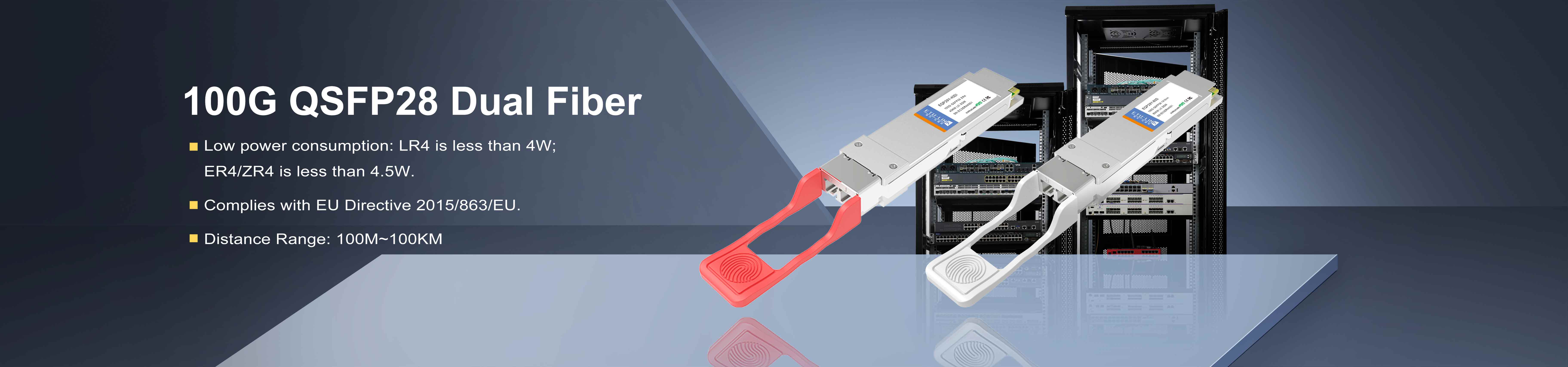
This solution supports smooth upgrade to 25G, 40G, 100G high-speed networks and meets long-term campus business growth.
Last updated: April 10, 2026
For inquiries about our products or pricelist, please leave your information with us and we will be in touch with in 24 hours.


 Factory: Right Side Of 3rd Floor, No. 102 Building, Longguan Expressway, Dalang Street, Longhua District, Shenzhen
Office: Floor 4, Building 4, Nanshan Yungu Phase ll, Taoyuan Community, XiliStreet,Nanshan District, Shenzhen
© Copyright: 2026 ETU-Link Technology CO ., LTD All Rights Reserved.

IPv6 network supported
Friendly Links:
易天官网