English


What is the cabling structure under the leaf ridge network?
As networks grow in size, we are seeing a shift from the traditional three-layer network architecture to a flatter, wider Spine-Leaf architecture. Most modern e-commerce, social media and cloud applications use distributed computing to serve their customers. Distributed computing means that servers speak to servers and work in parallel to create dynamic web pages and answer customer questions; it requires the same amount of delay. Waiting for results leaves customers unsatisfied. We need a network architecture that can grow uniformly and provide uniform latency for modern applications.
The solution to these problems comes from a network architecture, the "Spine-Leaf architecture". The idea has been around since 1952, when Charles Clos first introduced the multi-level circuit-switched network(also known as the Clos network). The backbone of this network architecture is called the Spine, and each Leaf is connected from the Spine to further extended network resources. By simply adding more Spine or Leaf switches, the network can grow evenly without changing the performance of the network. In this article, ETU-LINK takes a look at Spine switches, Leaf switches, and how they are wired to each other.
1. Spine Switch
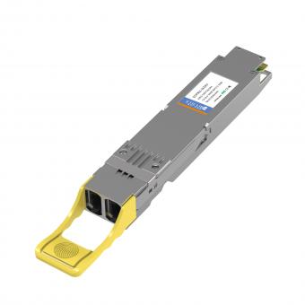
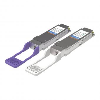
Spine switches can be 32*40G QSFP+ switches or 16*100G QSFP28 switches. Usually the number of available ports on a Spine Switch determines the number of Leaf switches that can be connected to the Spine, and thus the maximum number of servers that can be connected to the network.
2. Leaf switch
When choosing a Leaf switch, consider the number of uplink ports, which determines how many Spine switches can be connected to, in addition to the number of downlink ports, which determines the number of servers that can be connected to the Leaf switch.
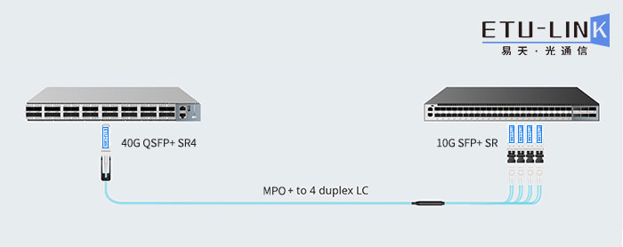
3. Spine-Leaf architecture cabling method
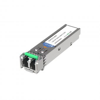
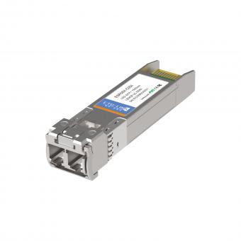
We can use ETU-LINK's 40G SR4 multimode optical module and 10G SR multimode optical module as the transmission solution. Usually Spin switches have 4 uplink ports, while Leaf switch ports have higher rates and more interfaces. Because 40G SR4 can be connected with 10G SR, we can insert 4 10G SR optical modules into the 10G SFP+ uplink ports on the Gigabit Spin switch, and 40G SR4 optical modules into the 40G QSFP+ ports on the Leaf switch, and finally connect them with MPO-LC fiber patch cable connections.
Data centers are shifting to Spine-Leaf architectures, and switch manufacturers have designed advanced switch systems for the next generation of data center switch architectures that can significantly reduce the complexity and connectivity costs of the data center fabric.
For inquiries about our products or pricelist, please leave your information with us and we will be in touch with in 24 hours.


 Factory: Right Side Of 3rd Floor, No. 102 Building, Longguan Expressway, Dalang Street, Longhua District, Shenzhen
Office: Floor 4, Building 4, Nanshan Yungu Phase ll, Taoyuan Community, XiliStreet,Nanshan District, Shenzhen
© Copyright: 2026 ETU-Link Technology CO ., LTD All Rights Reserved.

IPv6 network supported
Friendly Links:
易天官网