Today, ETU-Link will share the CFP2 optical module installation process with you. What preparations and attention should be made before installation? Let’s learn about it!
1. Preparation before installation
To avoid the static electricity generated during installation causes damage to CFP2 optical transceiver or electronic devices in equipment. Before installing or removing the CFP2 module, please wear the anti-static bracelet on your wrist, tighten the lock, make sure the anti-static bracelet is in good touch with the skin, and make sure that the anti-static bracelet is well grounded.
2. Installation and disassemble of CFP2 optical module
Warning: In the process of installing or pulling out the CFP2 optical module, please do not touch the gold finger of the CFP2 module with your hand directly.
Installation diagram of CFP2 module
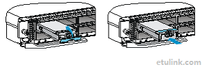
Turn the metal ring up vertically
According to the diagram, make sure that the module is installed in the right direction(The ring is located above the fiber optic interface). Push the module gently into the slot in the horizontal direction, until you hear the module blocking the slot. When the module is in close contact with the slot, no further push into the module.
Disassemble diagram of of CFP2 module
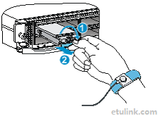 ★ Pull out the fiber on the CFP2 module and pull the metal ring down to the horizontal position
★ Pull the tab and pull the module out horizontally lightly, so as not to damage the ring.
3.Notice
◆ If the CFP2 module to be installed or disassembled is inserted with an optical fiber, please pull out the fiber and then install or disassemble the CFP2 module.
◆ When inserting the CFP2 module, check that the module is properly inserted into the port. Ensure correct orientation and no dislocation, offset, etc., and then push the module into place.
◆ When removing the CFP2 module, pull out the plug along the horizontal line.If there is an angle between the force direction and the horizontal direction, it will make it difficult to pull out the plug and even damage the module and slot.
◆ After finishing CFP2 module installation, if not immediately install fiber, please insert the dust plug.
Hope this blog can help you install and use CFP2 module. If you need CFP2 or CFP4 optical module, welcome to contact our sales: sales@etulinktechnology.com.
★ Pull out the fiber on the CFP2 module and pull the metal ring down to the horizontal position
★ Pull the tab and pull the module out horizontally lightly, so as not to damage the ring.
3.Notice
◆ If the CFP2 module to be installed or disassembled is inserted with an optical fiber, please pull out the fiber and then install or disassemble the CFP2 module.
◆ When inserting the CFP2 module, check that the module is properly inserted into the port. Ensure correct orientation and no dislocation, offset, etc., and then push the module into place.
◆ When removing the CFP2 module, pull out the plug along the horizontal line.If there is an angle between the force direction and the horizontal direction, it will make it difficult to pull out the plug and even damage the module and slot.
◆ After finishing CFP2 module installation, if not immediately install fiber, please insert the dust plug.
Hope this blog can help you install and use CFP2 module. If you need CFP2 or CFP4 optical module, welcome to contact our sales: sales@etulinktechnology.com.


 English


 Factory: Right Side Of 3rd Floor, No. 102 Building, Longguan Expressway, Dalang Street, Longhua District, Shenzhen